This is an old revision of the document!
Table of Contents
EPI Correction with polarity images using TOPUP
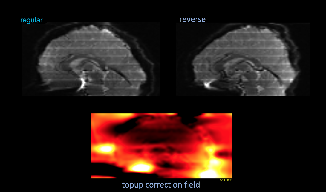
Steps to setup and apply FSL Topup correction on EPI data collected here with the use of your polarity images
Create your acquisition parameters
There will be two series of single timepoint EPI images. You can grab relevant info to create the acq_params.txt files from your XML header.
You need to calculate readout time in seconds ( the physical time it takes to get the acquisition matrix of a single slice ) and get the polarity direction ( phase encode direction ).
the readout time in seconds for the parameter file will be:
readout = (echospacing * (acquisitionmatrix[0] * (percentsampling/100))) / 1e6

echospacing in the BXH header is in microseconds
the polarity for the entry will have to be determined from the seriesdescription, which is typically “field map reverse polarity” or “field map regular”
reverse will be “-1” in the acq_params.txt and regular will be “1”
 echo '0 1 0 readout' > acq_params.txt
 echo '0 -1 0 readout' >> acq_params.txt

example output:
   0 1 0 0.077312
   0 -1 0 0.077312
Create your Blip Up/Down image
Merge the two polarity images together into a 4D file with fsl_merge. Put them in the order of your acq_params.txt file. In the example above, it would be regular, then reversed.
fslmerge -t bud ../bia6_00186_006.nii.gz ../bia6_00186_007.nii.gz

tesla:00273 cmp12$ fslinfo bud.nii.gz
    data_type      INT16
    dim1           128
    dim2           128
    dim3           70
    dim4           2
Run topup to calculate the field and coefficients images for correction
#run popup calculate the field/coef
topup --verbose --imain=bud --datain=acq_params.txt --config=$FSLDIR/src/topup/flirtsch/b02b0.cnf --out=rs_topup --fout=topup_field
Now apply the correction to your functional runs
inindex references the “regular” image index from your acq_params.txt file, which is the same phase encode direction of your functional runs
#apply it
applytopup --imain=../bia6_00186_008_01.nii.gz --inindex=1 --method=jac --datain=acq_params.txt --topup=rs_topup --out=run008 --verbose
applytopup --imain=../bia6_00186_009_01.nii.gz --inindex=1 --method=jac --datain=acq_params.txt --topup=rs_topup --out=run009 --verbose
applytopup --imain=../bia6_00186_010_01.nii.gz --inindex=1 --method=jac --datain=acq_params.txt --topup=rs_topup --out=run010 --verbose
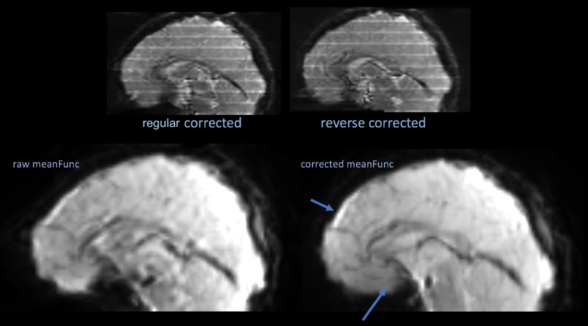
The top two images are an example of the polarity images after correction, which is not necessary. The bottom two images are the mean functional image of a series uncorrected, then corrected by the topup results.
If you want to re-generate a valid BXH for the corrected data, you can generate a new BXH and merge in the original info
fslwrapbxh run008
mv run008.bxh tmp.bxh
bxh_merge ../bia6_00186_008_01.bxh tmp.bxh run008.bxh
rm tmp.bxh
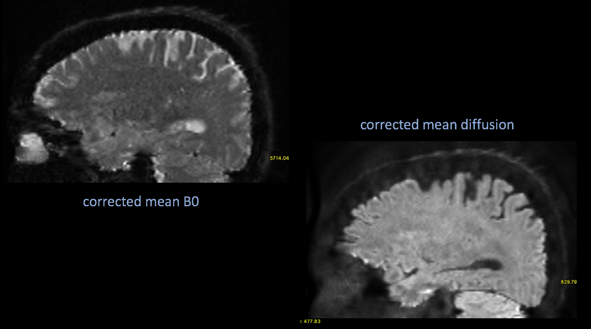
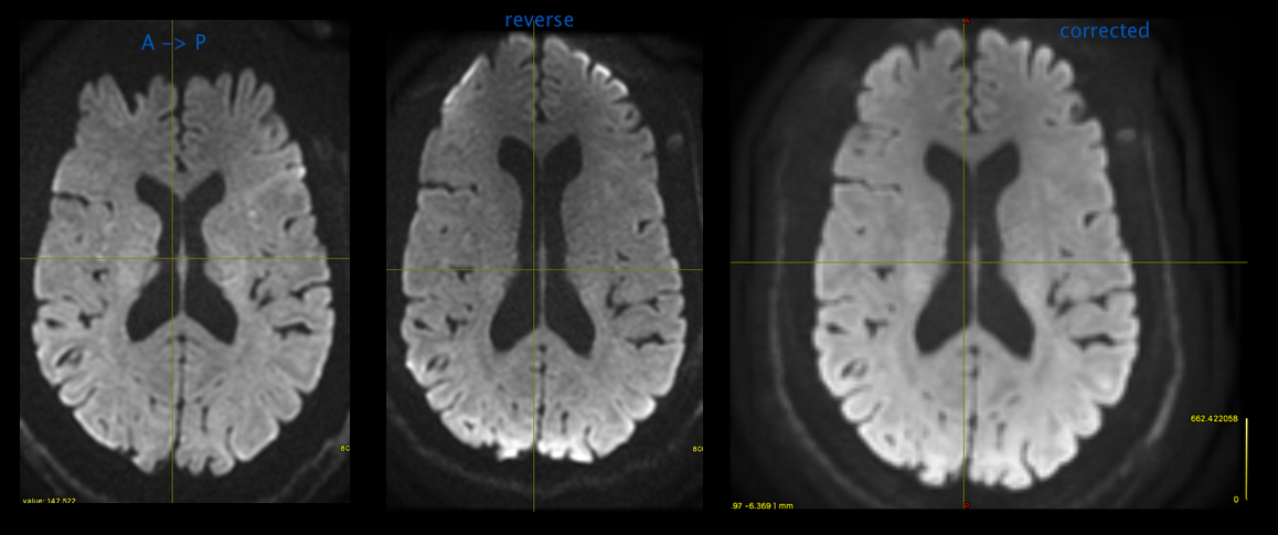
DWI Correction with RPE B0s using TOPUP
Correcting DWI images using reverse phase encoded B0s is almost the same as the above. Typically you'll have a couple B0s in your normal DWI acquisition, with a separate series of the same number of B0s collected with the phase encoding direction reversed.
Create your acq_params.txt file
the readout time in seconds for the parameter file will be:
readout = (echospacing * (acquisitionmatrix[0] * (percentsampling/100))) / 1e6

echospacing in BXH header is in microseconds
the regular B0s will get the “1” and the reverse phase B0s will get the “-1”
 echo '0 1 0 [readout]' > acq_params.txt
 echo '0 1 0 [readout]' >> acq_params.txt
 echo '0 -1 0 [readout]' >> acq_params.txt
 echo '0 -1 0 [readout]' >> acq_params.txt

example output:
   0 1 0 0.10656
   0 1 0 0.10656
   0 -1 0 0.10656
   0 -1 0 0.10656
Create your Blip Up/Down image
First, you'll need to extract your B0s from the regular DWI acquisition.
If you look at the gradient directions within the DWI acquisition the B0s will be “0 0 0”.
Within the BXH the first 2 directions are B0:
<datapoints label="diffusiondirection">
 <value>0 0 0</value>
 <value>0 0 0</value>
 <value>0.707107 0 0</value> <-- not a B0
Extract them with bxhselect:
bxhselect --timeselect 0:1 bia6_00197_012.bxh bu
bxhselect --timeselect 0:1 bia6_00197_013.bxh bd
This will create bu.nii.gz / bd.nii.gz with the first 2 gradient directions ( the B0s )
Now merge the extracted B0s from the regular acquisition with the images from the reversed acquisition. Merge these in the same order of the acq_params.txt file.
fslmerge -t bud bu.nii.gz bd.nii.gz

tesla:HCP cmp12$ fslinfo bud.nii.gz
data_type      INT16
dim1           256
dim2           256
dim3           92
dim4           4
Run topup to calculate the field and coefficients images for correction
#run popup calculate the field/coef
topup --verbose --imain=bud --datain=acq_params.txt --config=$FSLDIR/src/topup/flirtsch/b02b0.cnf --out=dwi_topup --fout=topup_field
Now apply the correction to your DWI
inindex references the “regular” dwi B0s index from your acq_para ms. txt file
#apply it
applytopup --imain=bia6_00197_012.nii.gz --inindex=1 --method=jac --datain=acq_params.txt --topup=dwi_topup --out=dwi_corrected --verbose
If you want to re-generate a valid BXH for the corrected data, you can generate a new BXH and merge in the original info
fslwrapbxh dwi_corrected.nii.gz
mv dwi_corrected.bxh tmp.bxh
bxh_addgradients --fsl tmp.bxh bvecs bvals dwi_corrected.bxh
rm tmp.bxh
DWI Correction with MRTRIX3 and RPE Data
mrtrix3 has a nice wrapper for FSL's eddy/topup/apply_topup that can do the above corrections and along with eddy corrections
If you are running dwidenoise, do it BEFORE dwipreproc.
Calculate your readout time
readout = (echospacing * (acquisitionmatrix[0] * (percentsampling/100))) / 1e6

echospacing in BXH header is in microseconds
Prepare your input datasets
there are 2 scenarios that typically apply here 1) a short acquisition with RPE B0s 2) an entire acquisition with the same gradient table and reverse phase encoding
In both scenarios it is important to create your data with normal phase encoding direction first, followed by reversed.
Scenario 1
Prepare your input datasets
Specify that a set of images (typically b=0 volumes) will be provided for use in inhomogeneity field estimation only
For scenario 1, create your blip up / blip down B0 data the same way as above.
bxhselect --timeselect 0 bi
a6_00197_012.bxh bu
bxhselect --timeselect 0 bia6_00197_013.bxh bd
fslmerge -t bud bu.nii.gz bd.nii.gz
rm bu.* bd.*
Prepare your dwi series for input to mrtrix3. If you use their mif data format, then the gradient tables will be automatically passed throughout their software with additional flags.
#pull the gradient table from BXH in FSL format
extractdiffdirs --fsl bia6_00414_013.bxh bvecs bvals

#convert nii.gz data into mif while inserting the gradients
mrconvert -fslgrad bvecs bvals bia6_00414_013.nii.gz dwi.mif

#export the table back out in their format
mrinfo dwi.mif -export_grad_mrtrix grads.b

#put THOSE back into the mif header
mrconvert -grad grads.b dwi.mif dwi.mif -force
The last step seems redundant, but there is an issue with how mrtrix3 tools are handling the multi-shell GE data produced on our scanners. If you data is NOT multi-shell, then you don't need it. If your data IS multi-shell, then putting it back in can workaround other issues until their RC4 code is released. discussion here
Run dwipreproc -rpe_pair
Run dwipreproc with the “-rpe_pair” option
dwipre
proc dwi.mif dwi_corr.mif -rpe_pair -se_epi bud.nii.gz -pe_dir AP -readout_time 0.10656  -debug

-rpe_pair specifies you're providing a pair of B0s ( regular, reversed )
-se_epi is you bud image
-pe_dir is your dwi's phase encode direction
-readout_time is from calculation above
dwipreproc will run topup, eddy and apply topup. eddy will output update diffusion directions and insert them into your dwi_corr.mif output header.
You can generate a BXH header for a mif file with:
mif2bxh dwi_corr.mif dwi_corr.bxh
Scenario 2
You have an entire acquisition with the same gradient table as your DWI sequence, but with reverse phase encoding. This information will be used to perform a recombination of image volumes (each pair of volumes with the same b-vector but different phase encoding directions will be combined together into a single volume).
Calculate the readout time in the same way as above
Prepare your input datasets
This time you'll concatenate the 2 DWI acquisitions. regular, then reversed
#concat the 2 series ( regular, reversed )
bxh_concat bia6_00260_007_LAS.bxh bia6_00260_008_LAS.bxh both

#extract the gradients
extractdiffdirs --fsl both bvecs bvals

#convert to mif
mrconvert -fslgrad bvecs bvals both.nii.gz dwi.mif

#re-extract table
mrinfo dwi.mif -export_grad_mrtrix grads.b

#put corrected table back in
mrconvert -grad grads.b dwi.mif dwi.mif -force

#remove the temporary files ( bvecs, bvals, both.* )


