Experimental Control System
Audio Switches
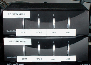
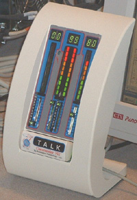
There are 4 switching boxes (Figures 1-3) that control how audio signals are routed throught the control systems at the MR scanners.
The first two (Figure 1) are push button boxes, each of which has 4 inputs and 1 output. The box labelled 'Headphones' selects which input goes to the subject's headphones inside the scanner. The box labelled 'PC Speakers' selects which input goes to the speakers on the table in the control room where the investigator sits.
For each box, the 4 inputs are:
- Computer 1
- Computer 2
- DVD player
- Auxiliary auditory
To get sound to the subject's headphones, the audio signal must pass through 2 more switch boxes. The white audio amplifier box (Figure 2) has a switch to select whether the sound to the headphones comes from the black Headphones switch box (Figure 1), or from the stereo entertainment system (see Stereo System).
That switch (labelled “Audio Input Selection”) has 2 modes:
- Audio – the stereo system is connected to the headphones
- Video – the black “headphones” audio switch is connected to the headphones (it must be in this mode to get computer or DVD sound)
Finally, sound to the headphones must pass through the headphone control box located on the MR console table (Figure 3). This box has 3 sets of volume controls. The leftmost is volume control for the headphone's microphone (listening to what the subject says). The middle set is balance control for sound sent to the headphone's left and right ears. The rightmost control is the master volume control to the headphones.


